


Microwave Link Budget & RF System Analyzer
Design microwave systems with comprehensive link budget analysis

What You Can Do
Calculate complete microwave link budgets including transmit power, antenna gains, path losses, noise figures, and system margins. Analyze RF component performance specifications, verify atmospheric conditions, and predict link availability. Generate structured design documentation with verification checklists and performance recommendations.
Features
Compute end-to-end link budgets with transmit power, amplifier gains, cable losses, antenna gains, and receiver sensitivity thresholds in dB notation.
Calculate system noise figure using cascade method, determine noise temperature, and evaluate impact on receiver performance across frequency bands.
Access specifications for antennas, amplifiers, cables, filters, and mixers including gain, loss, frequency ranges, and power handling capabilities.
Compute rain fade, oxygen absorption, water vapor attenuation, and free-space path loss for ground-to-satellite and terrestrial microwave links.
Evaluate antenna gain, directivity, radiation patterns, polarization, and beamwidth to optimize coverage and signal reception characteristics.
Calculate implementation margins, fading margins, and link availability percentages to ensure reliable operation under worst-case conditions.
Assess spectral efficiency, signal-to-noise ratio requirements, and throughput for different modulation schemes and coding rates.
Example Output
Link Budget Analysis for 15 GHz Terrestrial Link (50 km)
| Parameter | Value |
|---|---|
| Transmit Power | 20 dBm |
| TX Antenna Gain | 32 dB |
| Free-Space Path Loss | -149 dB |
| Rain Fade (0.01%) | -8 dB |
| RX Antenna Gain | 32 dB |
| Receiver Sensitivity | -85 dBm |
| Link Margin | +12 dB |
| Availability | 99.98% |
System Noise Figure
- LNA Gain: 28 dB, NF: 1.2 dB
- Mixer/IF Stage: NF 7 dB
- System NF: 1.4 dB, Noise Temp: 156 K
Antenna Performance
- Gain: 32 dBi, Beamwidth: 2.1 degrees
- Sidelobe Level: -25 dB
- 3dB Coverage Area: 2.1 km radius
Compliance Check: Link margin exceeds minimum 10 dB requirement. Expected EIRP within regulatory limits.
What's Included
- Link Budget Calculator: Automated computation of total path loss, system gain, and link margins with support for cascaded components and multi-hop paths.
- RF Component Library: Pre-configured specifications for common microwave components including amplifiers, antennas, cables, and passive devices across frequency bands.
- Atmospheric Loss Model: Calculations for rain fade, gaseous absorption, and free-space path loss with ITU recommendation implementations for reliable predictions.
- Performance Verification Checklist: Systematic verification of link margins, noise performance, antenna alignment, and compliance with regulatory requirements and design standards.
- Design Documentation Template: Structured markdown output including executive summary, system architecture, detailed calculations, and engineering recommendations.
- Parameter Sensitivity Analysis: Evaluate how variations in component specifications, weather conditions, or frequency affect link budget and system performance margins.
Who It's For
- RF Engineers designing microwave communication systems
- Satellite communications specialists evaluating ground-station links
- Wireless network architects deploying point-to-point microwave systems
- Telecommunications engineers optimizing spectral efficiency and coverage
- Systems engineers validating end-to-end link performance budgets
Best For
- Microwave terrestrial link design and optimization
- Ground-to-satellite and satellite-to-satellite link analysis
- RF component selection and compatibility verification
- Link availability prediction under atmospheric conditions
- Regulatory compliance verification and margin validation
You might also like

You upload OTDR (Optical Time Domain Reflectometer) test traces or raw test data, and this skill interprets the results to identify fault locations, measure signal degradation, and recommend remediation steps. It accelerates troubleshooting by automating trace analysis and generating professional diagnostic reports that pinpoint connector losses, splice issues, and cable faults with exact distance measurements.
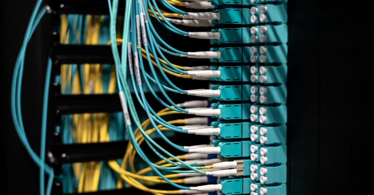
You can upload fiber optic test data (OTDR, reflectance, attenuation measurements) and receive automated analysis with root cause identification, performance metrics, and optimization recommendations. The skill generates professional troubleshooting reports highlighting problem areas, estimated repair costs, and compliance status against industry standards like TIA-942 and IEC 60793.

This skill assesses electromagnetic compatibility and interference risks in your product design, identifies compliance gaps against international standards (FCC, CE, RoHS), and generates targeted mitigation strategies. You get a structured compliance roadmap with design recommendations, test planning guidance, and regulatory requirements specific to your product category and target markets.

This skill helps you design efficient fiber optic network routes, estimate project costs, map regulatory compliance requirements, and generate comprehensive deployment documentation. You get detailed route analysis, material cost breakdowns, timeline estimates, and compliance checklists that accelerate planning while reducing risk and identifying cost-saving opportunities.

You can evaluate WAN technologies (MPLS, SD-WAN, DIA, broadband), design resilient multi-site architectures, perform detailed cost-benefit analysis, and assess technology and operational risks. Claude helps you create comprehensive network design recommendations with topology diagrams, technology comparisons, ROI projections, and implementation roadmaps tailored to your business requirements and constraints.
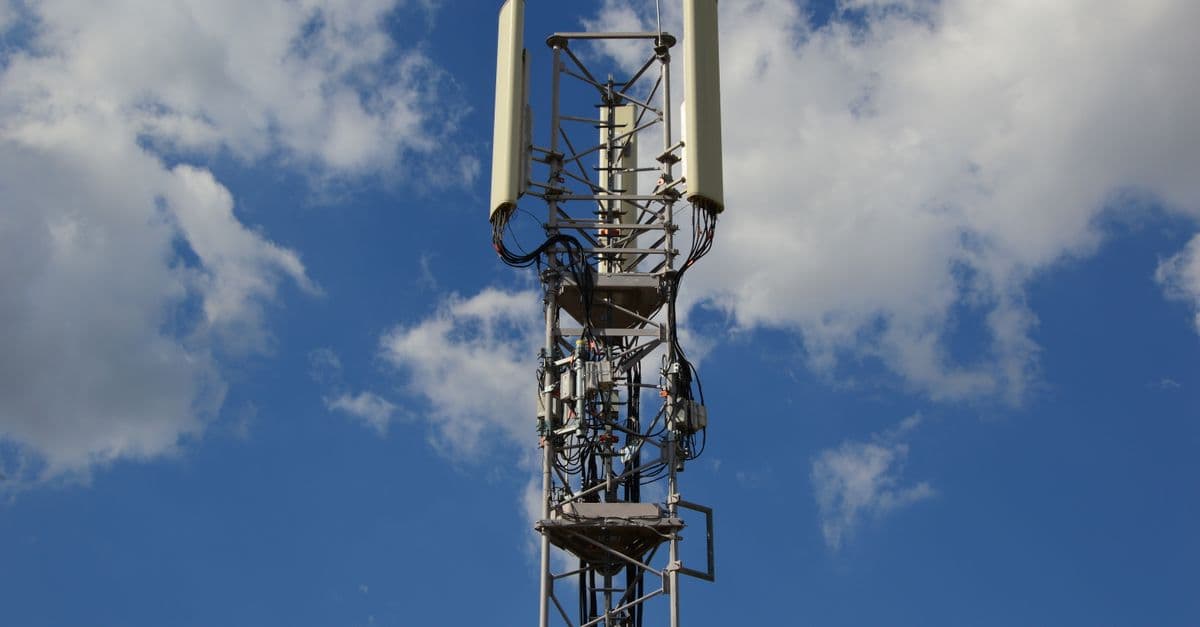
This skill equips you to analyze fiber-to-the-home network architectures, diagnose optical performance problems, and generate comprehensive deployment documentation. You can evaluate network requirements, calculate capacity metrics, identify bottlenecks, and produce professional technical reports that guide installation and optimization efforts.

Model how radio waves propagate through environments using empirical and theoretical approaches. Calculate link budgets, predict signal strength at specific locations, and diagnose coverage gaps using measurement data. Claude analyzes your propagation models, suggests optimizations, and interprets measurement results in the context of standard RF theory.

Get expert guidance on antenna design, from type selection to performance optimization. This skill walks you through electromagnetic calculations, feed network analysis, and construction considerations to help you design antennas that meet your frequency, gain, and bandwidth requirements. Whether you're working with microstrip patches, dipoles, or horn antennas, you'll receive step-by-step design recommendations tailored to your specifications.