

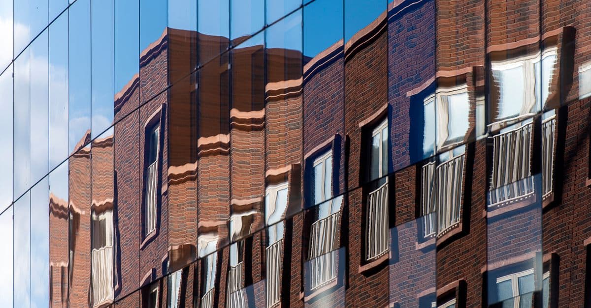
Facade Thermal Bridge Analysis & Mitigation
Identify and mitigate thermal bridges in building envelopes using ISO 10211 methodology
What You Can Do
You can map thermal bridge locations in building envelopes, quantify their effect on overall facade thermal performance (U-value degradation), assess condensation formation risk through surface temperature analysis, and develop detailed mitigation strategies aligned with energy codes and construction feasibility. Claude helps you bridge the gap between idealized thermal calculations and actual building performance by integrating linear and point thermal transmittance into energy models.
Features
Systematically identify weak points at structural connections, window frames, balcony attachments, and material transitions
Apply standardized methodology for calculating linear thermal transmittance (Ψ-value) and point thermal transmittance (χ-value)
Calculate how thermal bridges reduce overall facade thermal performance by 15-30% and factor degradation into energy modeling
Analyze interior surface temperatures against dew point conditions to identify mold and moisture damage risk zones
Model heating/cooling load impacts from thermal bridging and compare mitigation scenarios
Develop targeted solutions (thermal breaks, material optimization, structural detailing) with cost-performance trade-offs
Align designs with maximum U-value requirements, minimum surface temperature thresholds, and building energy standards
Evaluate alternative systems (material, insulation placement, structural approach) to optimize thermal performance
Example Output
Example 1: Window Frame Thermal Bridge Analysis
- Identified: Aluminum frame connection at facade plane with structural anchors
- Linear transmittance (Ψ): 0.18 W/mK (unmitigated)
- Impact on facade U-value: +0.032 W/m²K (18% degradation)
- Surface temperature at frame interior: 8.2°C (condensation risk at 45% RH)
- Mitigation: Thermal break inserts + inboard frame placement
- Revised Ψ-value: 0.06 W/mK (-67% improvement)
- Revised facade U-value: 0.125 W/m²K (meets Passivhaus requirement)
Example 2: Balcony Attachment Strategy
- Comparison of three detailing approaches with thermal and cost analysis
- Standard steel bracket: χ = 0.15 W/K, cost baseline
- Fiberglass composite bracket with thermal break: χ = 0.04 W/K, +15% material cost
- Structural separation (cantilevered): χ = 0.01 W/K, +45% structural cost
- Recommendation: Composite bracket balances performance and feasibility for mid-rise residential
What's Included
- SKILL.md: Complete instruction file with thermal bridge analysis methodology
- ISO 10211 Calculation Template: Worksheet for Ψ-value and χ-value determination
- Thermal Bridge Mapping Checklist: Systematic walkthrough of facade details and connection points
- Condensation Risk Assessment Framework: Surface temperature analysis and mold risk evaluation criteria
- Mitigation Strategy Comparison Matrix: Side-by-side thermal performance, cost, and constructability evaluation
Who It's For
- Facade engineers designing building envelopes and curtain wall systems
- Energy modelers and building performance consultants optimizing thermal efficiency
- Architects and building science specialists pursuing Passivhaus or net-zero certifications
- Building envelope retrofit specialists tackling existing facade condensation and energy issues
- Building code compliance consultants verifying U-value and surface temperature requirements
Best For
- Thermal bridge identification at structural connections and material transitions
- U-value calculations incorporating linear and point thermal transmittance
- Condensation risk assessment and interior surface temperature analysis
- Mitigation strategy development with thermal performance and cost trade-off evaluation
- Code compliance verification against energy standards and building regulations
- Comparison of facade system alternatives (insulation placement, thermal breaks, structural approach)
You might also like

You'll build complete PayPal payment workflows that handle transactions, refunds, and subscriptions with production-ready error handling. This skill walks you through REST API authentication, webhook configuration, and debugging common payment issues so your integration handles real-world scenarios.
 by aharstad91
You can generate complete environmental noise impact assessments (NIAs) that characterize baseline conditions, identify noise sources, map sensitive receptors, interpret predictive modeling outputs, and evaluate compliance against EPA guidelines, OSHA standards, and local ordinances. The framework guides you through cumulative impact analysis and helps you develop technically defensible mitigation recommendations that balance regulatory requirements with project feasibility and budget constraints.
by aharstad91
You can systematically evaluate auditorium acoustic performance by inputting measured data (impulse response, RT60, speech intelligibility metrics) or simulation results, then receive detailed analysis identifying specific frequency-dependent problems, quantified deviations from ISO 3382 and AES standards, and prioritized remediation strategies. Claude cross-references your data against performance benchmarks and generates technical justifications suitable for architect presentations, client reports, and construction specifications.
by aharstad91
You can input architectural parameters, environmental data, and code requirements to automatically calculate simultaneous loads on glass assemblies, determine minimum glass thickness and support specifications, and generate glazing schedules and stress reports. This eliminates manual load case combinations and identifies design conflicts before fabrication, ensuring compliance with building codes and reducing engineering rework.
by aharstad91
You can conduct comprehensive acoustic compliance assessments for building projects by evaluating designs against applicable codes (IBC, local ordinances, ANSI standards), identifying sound transmission class (STC) and noise criteria (NC) deficiencies, and recommending prioritized mitigation strategies with cost-benefit analysis. This skill structures your assessment to capture environmental noise exposure, internal noise levels, speech intelligibility, vibration isolation, and impact sound transmission—delivering actionable compliance documentation for permitting, certification, or remediation planning.
by aharstad91
You can systematically evaluate room acoustic conditions by calculating reverberation times (RT60) using Sabine formulas, identifying problem frequencies and room modes, analyzing absorption material performance across frequency ranges, and generating detailed acoustic treatment specifications with scientific justification. The skill produces professional-grade acoustic solutions tailored to your space constraints, budget, and performance targets while maintaining compliance with standards like ISO 3382 and ASTM C423.
by aharstad91
You'll conduct comprehensive corporate space assessments that synthesize employee needs, business workflows, brand strategy, and budget realities into actionable design solutions. Claude helps you diagnose spatial performance issues, generate evidence-based recommendations, validate design choices against measurable outcomes, and create scalable guidelines for multi-location implementations. You'll move beyond aesthetic preferences to deliver spaces that demonstrably support productivity, wellness, and organizational goals.
by aharstad91
You can rapidly evaluate smoke control system designs by calculating required pressurization differentials, airflow requirements, and fan capacity specifications. The skill validates compliance against NFPA 92, IBC Chapter 9, and local amendments while analyzing integration points with HVAC and fire alarm systems. It identifies design gaps, suggests optimization opportunities, and generates technical documentation to support the full design lifecycle from concept through commissioning.
by aharstad91