

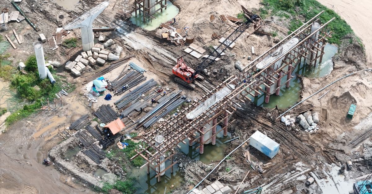
Earth Retention Design Assistant
Analyze soil conditions and generate compliant earth retention wall designs with pressure calcula...
What You Can Do
You can input site investigation data, soil parameters, and project constraints to receive complete earth pressure distributions, structural design requirements, and load case verification documentation. The skill handles pressure coefficient selection, external stability checks (overturning, sliding, bearing capacity, global stability), internal capacity verification, and constructability review for gravity walls, cantilever walls, sheet pile systems, soldier pile walls, and tieback configurations. This accelerates preliminary and detailed design phases while maintaining engineering judgment on load combinations and deformation criteria.
Features
automatically selects active, at-rest, or passive pressure regimes based on soil type and wall movement
systematizes multiple design conditions (permanent loads, surcharge, water, seismic, construction phasing) into structured pressure diagrams
checks overturning, sliding, bearing capacity, and global slope stability with code-aligned safety factors
calculates bending moments, shear forces, and reinforcement requirements for concrete walls or section capacity for steel systems
evaluates impact of soil parameter uncertainty on wall dimensions and design feasibility before final selection
identifies access constraints, embedment feasibility, adjacent structure impacts, and phasing considerations
organizes calculations, diagrams, and verification summaries in engineer-ready format for compliance review
Example Output
Input: 35-foot cantilever wall retaining 25-foot fill on medium dense sand (φ=36°, γ=120 pcf), with surcharge traffic load and water table at base.
Generated Output:
- Active earth pressure diagram: 1,240 psf at base, triangular distribution, with dynamic increment for seismic conditions
- Critical load cases organized: Permanent loads (gravity + surcharge) → maximum moment at 12 ft depth = 1,850 kip-ft/ft
- External stability summary: Overturning ratio = 2.1 ✓ | Sliding ratio = 1.6 ✓ | Base bearing = 4,200 psf (allowable 5,500) ✓
- Reinforcement design: #8 @ 8" vertical, #6 @ 12" horizontal (based on 50 ksi yield, 3,500 psi concrete)
- Constructability notes: 4-ft embedment adequate; groundwater control required during excavation; adjacent 12-ft easement confirms tie-back feasibility
What's Included
- SKILL.md: full earth retention design methodology
- Soil Parameter Worksheet: template for organizing site investigation data, stratification, and lab test results
- Pressure Calculation Framework: step-by-step guidance for active/passive/at-rest coefficient selection and load case development
- Stability Check Matrix: organized verification table for external (overturning, sliding, bearing, global) and internal (section capacity) checks
- Design Sensitivity Template: structured format for testing soil parameter assumptions and wall configuration variations
Who It's For
- Geotechnical engineers designing and verifying earth retention structures
- Civil engineers developing structural solutions for excavation support and slope stabilization
- Project engineers coordinating constructability and phasing with retention design
- Junior engineers building systematic design documentation under senior review
- Design review consultants organizing calculations and verification for compliance audit
Best For
- Preliminary design phase exploring wall height, batter, embedment, and configuration trade-offs
- Pressure calculation and load case organization for walls 8–40 feet in defined soil stratification
- External and internal stability verification against code-aligned safety factors
- Sensitivity analysis testing impact of soil parameter uncertainty on design feasibility
- Design documentation compilation and cross-check before compliance submission
You might also like

Query your local Screenpipe instance to retrieve screen recordings, audio transcriptions, UI element accessibility trees, keyboard/mouse input logs, and productivity analytics. You can search by keywords, filter by content type (audio, OCR, accessibility, input), set time ranges, and extract structured data about your applications, meetings, and work sessions without sending data to external servers.
 by az9713
This skill automates the detailed calculations required for electrical system design, converting connected loads to demand loads, sizing conductors and equipment per NEC standards, and analyzing voltage drop across feeders and branch circuits. You input project parameters and receive complete load schedules, equipment recommendations with ampacity ratings, conductor specifications, and code citations—eliminating manual calculation errors and enabling faster design iterations for permit-ready documentation.
by az9713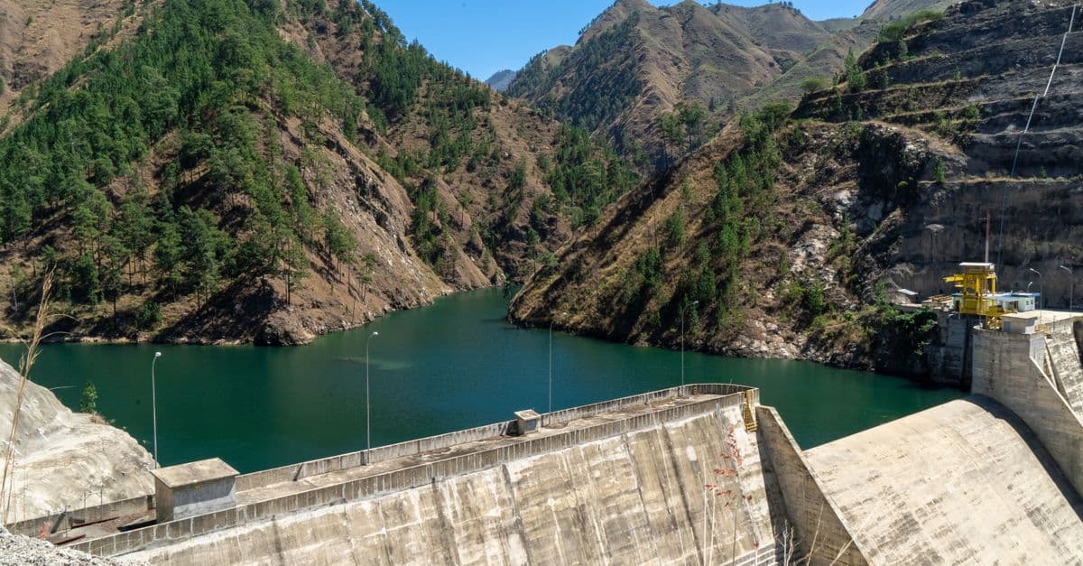
You can conduct comprehensive slope stability analyses that integrate site characterization, soil/rock properties, and quantitative calculations to evaluate both simple and complex slope geometries. The framework helps you identify critical failure mechanisms, calculate safety factors, assess groundwater and seismic effects, and develop technically defensible remediation recommendations suitable for permitting, design decisions, and stakeholder communication.
by az9713
You can systematically design test cases for any feature or system by analyzing requirements or code to extract test parameters, values, and business constraints. The skill generates a PICT model, executes pairwise testing logic to minimize test case count while maximizing coverage, and delivers a formatted test matrix with expected results—reducing manual test design effort while ensuring comprehensive scenario coverage.
by az9713
This skill deconstructs your writing samples to identify the specific patterns, personality markers, emotional range, language quirks, and formatting habits that make your voice uniquely yours. You'll receive a detailed voice DNA profile that includes your core communication style, signature phrases, emotional tone, formality level, and what you actively avoid—creating a blueprint that AI systems can use to replicate your authentic voice consistently across projects, platforms, and content types.
by az9713
You can decompose complex timber structures into analyzable load paths, trace forces from applied loads through members to supports, and calculate governing demands for each structural element. This skill helps you identify critical design points, apply appropriate load factors and duration adjustments, and create defensible design documentation that satisfies code officials and peer reviewers.
by az9713
You can compare building materials across embodied carbon, water usage, recyclability, supply chain impacts, and lifecycle costs—all grounded in industry standards like EN 15804 and ISO 14040/44. This skill transforms material selection from intuition-based guessing into data-driven specification, producing analysis outputs ready for client presentations, value engineering discussions, and regulatory compliance documentation.
by az9713
You can accelerate HVAC design workflows by inputting building parameters—envelope characteristics, occupancy data, climate conditions, and existing systems—and receiving calculated heating/cooling loads, equipment sizing recommendations, and zone-by-zone analysis. Claude organizes complex building data into actionable design parameters and specification summaries for client review, permit submission, and professional validation against ASHRAE and ACCA standards.
by az9713