


Antenna Performance Analyzer
Derive antenna optimization strategies from simulation data

What You Can Do
Upload or paste antenna simulation results, and Claude analyzes electrical characteristics to identify performance bottlenecks and recommend targeted optimizations. You get actionable design changes for gain improvement, impedance matching, radiation pattern refinement, and bandwidth expansion. The skill interprets industry-standard formats and translates complex electromagnetic data into engineering insights.
Features
Extract directivity and realized gain metrics, identify frequency-dependent gain variations, and recommend geometric adjustments to maximize radiation efficiency
Analyze S-parameters and return loss across frequency bands, pinpoint impedance discontinuities, and suggest matching network topologies or geometry modifications
Assess 2D and 3D far-field patterns for sidelobe levels, null steering, and main lobe directivity, then propose element repositioning or feed adjustments
Identify frequency-dependent performance limits, quantify impedance bandwidth and gain flatness, and recommend scaling or tuning strategies
Compare multiple antenna designs side-by-side across gain, efficiency, pattern, and bandwidth metrics to highlight trade-offs and guide design selection
Analyze element-to-element coupling effects in arrays, quantify coupling coefficients, and recommend spacing or decoupling network solutions
Prioritize competing objectives (gain vs. size, bandwidth vs. impedance match) and generate Pareto-optimal design recommendations
Example Output
Input: S-parameters and gain data from a 5 GHz patch antenna simulation.
Output:
- Gain is 6.2 dBi but drops 1.8 dB at band edges (4.8-5.2 GHz). Primary cause: impedance mismatch worsens at frequencies away from center.
- Impedance varies from 35 ohms at 4.8 GHz to 65 ohms at 5.2 GHz. Add a quarter-wave transformer or capacitive stub to flatten to 50 ohms across band.
- Sidelobe level at 5 GHz is -10 dB. Recommend reducing ground plane size by 5% or adding parasitic elements to suppress sidelobe.
- Estimated improvement: +1.2 dB gain flatness and -3 dB sidelobe reduction after implementing stub and ground plane adjustment.
Another example: Array mutual coupling analysis shows 12 dB isolation degradation between adjacent dipoles at 2.4 GHz. Recommend 0.4-wavelength spacing (instead of 0.3) or a resistive isolation network on the feedline.
What's Included
- Antenna Analysis Templates: Pre-built prompt structures for gain, impedance, pattern, and bandwidth analysis workflows
- Data Format Guide: Reference for common simulation output formats (S-parameters, VSWR, radiation patterns) and how to structure data for Claude interpretation
- Optimization Recommendation Framework: Structured methodology for translating simulation metrics into ranked design changes with predicted performance deltas
- Comparative Design Checklist: Systematic checklist for evaluating and scoring multiple antenna variants against performance criteria
Who It's For
- RF and Microwave Engineers
- Antenna Design Specialists
- Wireless Systems Engineers
- EMC and EMI Professionals
Best For
- Post-simulation analysis and design iteration
- Rapid performance bottleneck identification
- Design trade-off evaluation and comparison
- Optimization strategy prioritization
You might also like
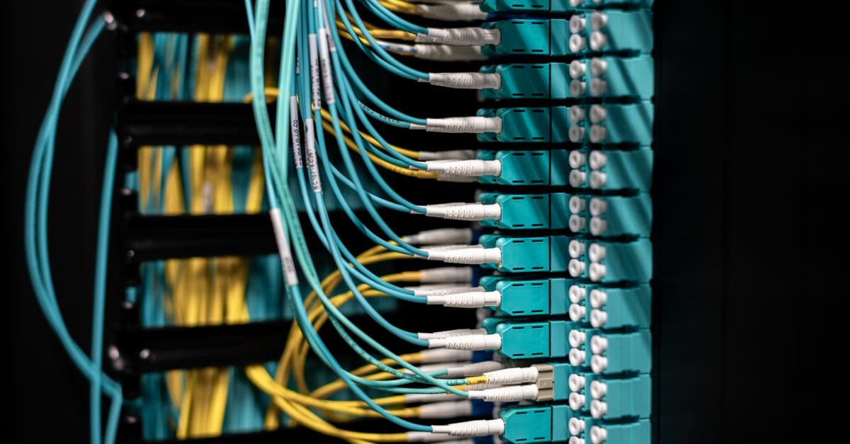
You can upload fiber optic test data (OTDR, reflectance, attenuation measurements) and receive automated analysis with root cause identification, performance metrics, and optimization recommendations. The skill generates professional troubleshooting reports highlighting problem areas, estimated repair costs, and compliance status against industry standards like TIA-942 and IEC 60793.

Systematically analyze your cloud network architecture across security, resilience, cost, and compliance dimensions. You receive a comprehensive assessment report with prioritized optimization recommendations, security hardening steps, and implementation guidance tailored to your infrastructure. The skill evaluates network design patterns, resource utilization, and compliance gaps to help you build cost-effective, secure, and highly available cloud networks.

You upload OTDR (Optical Time Domain Reflectometer) test traces or raw test data, and this skill interprets the results to identify fault locations, measure signal degradation, and recommend remediation steps. It accelerates troubleshooting by automating trace analysis and generating professional diagnostic reports that pinpoint connector losses, splice issues, and cable faults with exact distance measurements.

Model how radio waves propagate through environments using empirical and theoretical approaches. Calculate link budgets, predict signal strength at specific locations, and diagnose coverage gaps using measurement data. Claude analyzes your propagation models, suggests optimizations, and interprets measurement results in the context of standard RF theory.

You can design antennas optimized for your specific frequency range and use case, then instantly analyze their predicted performance including gain, radiation patterns, and impedance characteristics. Get actionable recommendations for geometry refinements, matching networks, and feed methods tailored to your constraints. Transform RF design from guesswork into a methodical process with detailed parameter specifications ready for simulation or prototyping.

Calculate complete microwave link budgets including transmit power, antenna gains, path losses, noise figures, and system margins. Analyze RF component performance specifications, verify atmospheric conditions, and predict link availability. Generate structured design documentation with verification checklists and performance recommendations.

This skill assesses electromagnetic compatibility and interference risks in your product design, identifies compliance gaps against international standards (FCC, CE, RoHS), and generates targeted mitigation strategies. You get a structured compliance roadmap with design recommendations, test planning guidance, and regulatory requirements specific to your product category and target markets.
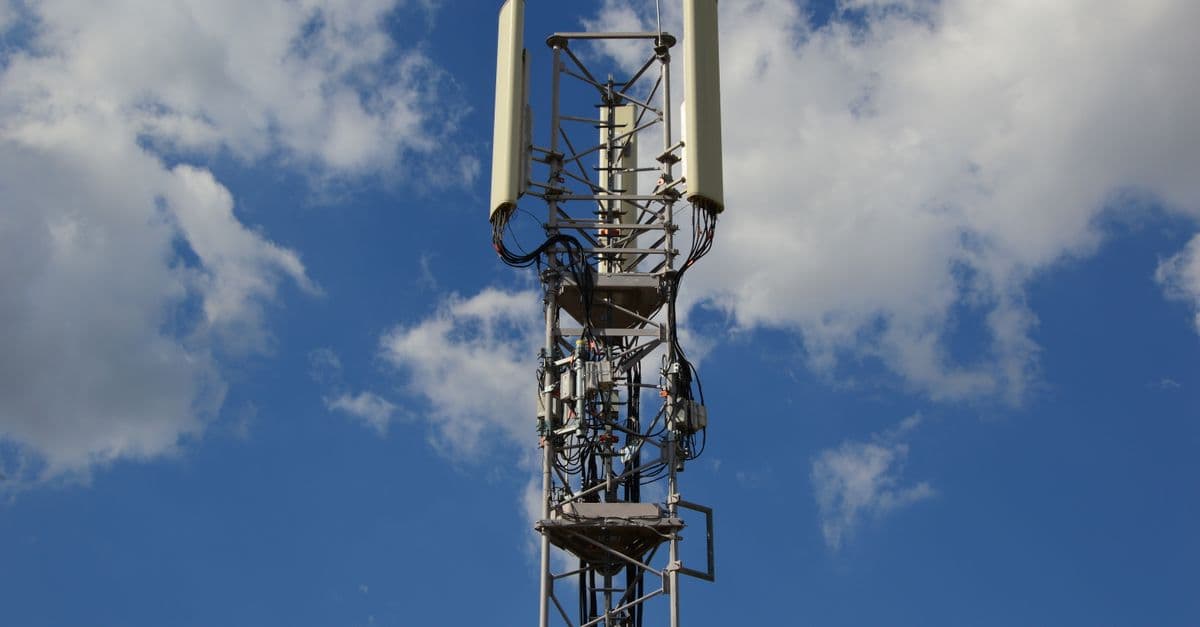
This skill equips you to analyze fiber-to-the-home network architectures, diagnose optical performance problems, and generate comprehensive deployment documentation. You can evaluate network requirements, calculate capacity metrics, identify bottlenecks, and produce professional technical reports that guide installation and optimization efforts.