


Control Loop Diagnostics for Robotics
Debug PID systems and control loops with data-driven diagnostics

What You Can Do
You can upload time-series control loop data and Claude will diagnose oscillations, identify stability issues, and evaluate tuning parameters. The skill analyzes your signal characteristics, quantifies steady-state error and overshoot, and generates actionable tuning recommendations backed by system identification metrics. You'll receive prioritized root-cause analyses and concrete parameter adjustment guidance to stabilize your feedback control systems.
Features
distinguish between sensor noise, PID tuning problems, and fundamental instability
assess proportional, integral, and derivative gains against ideal ranges for your system type
decompose noise from real system dynamics using frequency-domain inspection and step-response metrics
quantify offset, settling time, overshoot, and rise time against performance targets
compute phase margin, gain margin, and damping ratio from your measured response data
generate specific Kp/Ki/Kd adjustment suggestions with predicted impact on system behavior
evaluate before/after control loop performance across multiple tuning iterations
structured findings with visualizations, severity ratings, and implementation priority
Example Output
Example 1: Oscillation Diagnosis
- 🔴 CRITICAL: Sustained oscillation detected
Frequency: 12 Hz | Amplitude: ±2.3V | Damping ratio: 0.15 (unstable)
Root Cause: Over-tuned derivative gain amplifying sensor noise
Recommendation: Reduce Kd from 0.85 to 0.35, add 50ms low-pass filter
Example 2: Tuning Adjustment Report
- ✅ Current: Kp=1.2, Ki=0.05, Kd=0.8
- ⚠️ Issues: 18% overshoot, 320ms settling time (target: 200ms)
- ✅ Proposed: Kp=0.8, Ki=0.08, Kd=0.4
- 📊 Expected improvement: 6% overshoot, 185ms settling, ±0.02V steady-state error
What's Included
- SKILL.md: Complete diagnostic workflows for PID analysis, sensor evaluation, and root-cause debugging
- PID Tuning Template: Step-by-step worksheet for documenting system characteristics and evaluating parameter ranges
- Data Analysis Checklist: Verification steps for signal quality, noise floor assessment, and stability metrics
- Signal Inspection Guide: Decision tree for identifying oscillation sources (derivative kick, integral windup, sensor noise)
- System Identification Reference: Quick-lookup tables for expected response characteristics by control system type
- Diagnostic Report Template: Structured format for findings, severity levels, and prioritized recommendations
Who It's For
- Robotics engineers tuning motion control and joint feedback loops
- Control systems engineers troubleshooting PID implementations
- Hardware engineers debugging actuator response and stability issues
- Embedded systems developers integrating servo motors or stepper feedback
- Mechanical engineers optimizing precision positioning systems
Best For
- Diagnosing oscillating or unstable control loops
- Evaluating and adjusting PID tuning parameters
- Distinguishing sensor noise from real system problems
- Analyzing step response data and identifying transient issues
- Creating diagnostic reports and tuning change justifications
You might also like

This skill enables you to automatically audit your websites against compliance standards and detect deviations from expected baselines. You can track regulatory requirements, identify policy violations, and generate compliance reports with actionable remediation steps. Monitor multiple sites simultaneously and maintain detailed audit trails for compliance documentation.
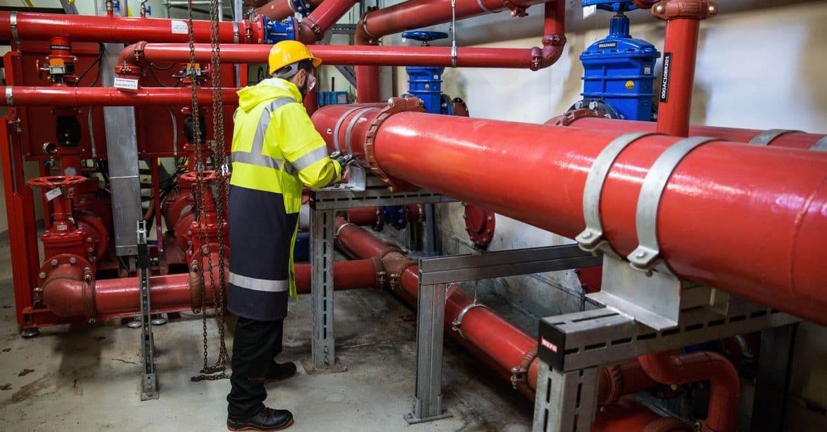
Analyze chemical processes systematically to identify hazards, assess risks, and generate safety recommendations. You can perform HAZOP analyses, evaluate compliance with industry standards, conduct root-cause analysis of incidents, and develop emergency response procedures. The skill guides you through structured safety reviews that reduce the likelihood of accidents and regulatory violations.

You'll develop systematic approaches to injectable formulation design, from API selection through sterilization strategy. Claude helps you troubleshoot failed batches by analyzing root causes, recommends regulatory pathways (505(b)(2), ANDA, NDA), and provides science-backed solutions for stability, compatibility, and manufacturability challenges.
This skill helps you systematically assess integration needs across your systems, design architecture patterns that scale with your organization, and identify technical and operational risks before implementation. You'll receive architecture recommendations aligned to your business constraints, clear integration roadmaps, and risk mitigation strategies that reduce deployment surprises. Get structured decision records suitable for architecture review boards and engineering teams.

You can conduct comprehensive hazard analyses for chemical processes using industry-standard methodologies like HAZOP and LOPA. The skill helps you assess risks quantitatively, identify control gaps, design engineered safeguards, and generate formal documentation for regulatory compliance and process safety management.

Claude analyzes your code diffs and generates standardized commit messages that follow the Conventional Commits specification. The skill automatically determines the correct commit type, scope, and description based on the changes you've made, ensuring your messages are parseable by automation tools while remaining human-readable for code reviewers.

You can transform raw text into structured, labeled datasets for machine learning, analysis, and research. This skill performs named entity recognition, sentiment classification, part-of-speech tagging, and dependency parsing—generating consistent, validated annotations at scale. Use it to prepare corpora, extract entities, classify documents, or perform linguistic analysis without manual annotation.
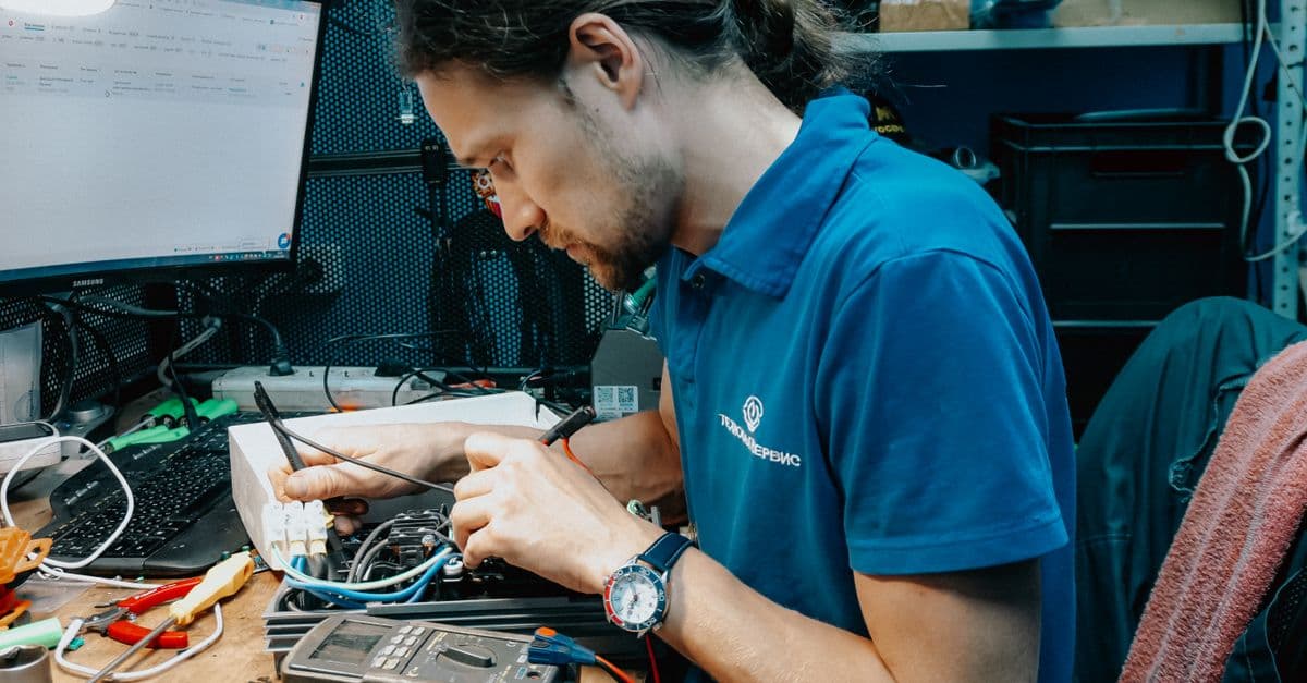
Rapidly analyze firmware logs and diagnose hardware issues that cause device failures, connectivity problems, and performance degradation. You'll identify root causes from stack traces, crash dumps, and sensor data, then generate specific optimization recommendations. This skill transforms raw device logs into actionable debugging plans that reduce time-to-resolution from hours to minutes.